Electronic Science - Online Test
Q1. A two – bit counter circuit is shown below

It the state QAQB of the counter at the clock time tn is ‘10’ then the state QAQB of the counter at tn + 3 (after three clock cycles ) will be
Answer : Option C
Explaination / Solution:

Q2. 
The Boolean expression for the output f of the multiplexer shown below is
Answer : Option A
Explaination / Solution:
No Explaination.
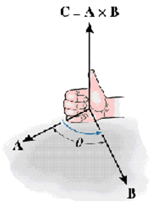
Q3. direction of magnetic force on a positive charge moving in a magnetic field is given by
Answer : Option C
Explaination / Solution:
The force experienced by a charged particle in a magnetic field is given by .The right hand rule for vector product can be used to determine the direction of .
Q4. The bridge method commonly used for finding mutual inductance is
Answer : Option A
Explaination / Solution:
No Explaination.
Q5. Potentiometer measures the potential difference more accurately than a voltmeter, because
Answer : Option D
Explaination / Solution:
Potentiometer measures the potential difference using null deflection method, where no current is drawn from the cell; whereas voltmeter needs a small current to show deflection. So, accurate measurement of p.d is done using a potentiometer.
Q6. Which of the following statements about magnetic field lines true?
Answer : Option D
Explaination / Solution:
No Explaination.
Q7. Hole is a vacancy or lack of an electron and can travel through the semiconductor material. It can
Answer : Option C
Explaination / Solution:
Holes and electrons are the two types of charge carriers responsible for current in semiconductor materials.
Holes in a metal or semiconductor crystal lattice can move through the lattice as electrons can, and act similarly to positively-charged particles. They play an important role in the operation of semiconductor devices such as transistors, diodes and integrated circuits. However they are not actually particles, but rather quasiparticles; they are different from the positron, which is the antiparticle of the electron.
Q8. In the circuit shown below what is the output voltage out (Vout) in Volts if a silicon
transistor Q and an ideal op-amp are used?

Answer : Option B
Explaination / Solution:
No Explaination.
Q9. For the BJT circuit shown, assume that the β of the transistor is very large and VBE = . V. The mode of operation of the BJT is

Answer : Option B
Explaination / Solution:

Q10. In circuits, a difference in potential from one point to another is often called
Answer : Option A
Explaination / Solution:
Voltage is the common term used for potential difference or e m f.
